Design Recommendations for SLS 3D Printing
At a Glance
-
Complex geometries and undercuts are not a problem
-
Largest build space: 340 x 340 x 600 mm
-
Layer thickness 0.1 or 0.12 mm
-
Minimum wall thickness: 0.6 mm
-
Threads from M4 can be produced directly in the SLS process
-
Film hinges can be produced directly using SLS
-
Minimum font height: 3.5 mm
-
Inscription should be at least 0.5 mm recessed or raised
-
Tolerance range: 0 to 30 mm approx. ± 0.2 mm, 30 to 100 mm approx. ± 0.3 mm, from 100 mm approx. ± 0.3% of the nominal dimension (Does not apply to bores and inner diameters)

Wall thicknesses and rod diameters
The minimum wall thickness for SLS components is approximately 0.6 mm in the X, Y, and Z directions, while the smallest printable rod diameter is approximately 0.8 mm. However, for repeatable measurement results and reproducible mechanical properties, we recommend a wall thickness of at least 1.5 mm and a rod diameter of at least 1.8 mm. Even for series parts, a wall thickness of at least 1.5 mm should be maintained to ensure consistently high component quality.

Bores
For each wall thickness, there is a minimum diameter for a bore that can be produced directly in the SLS process. Smaller diameters usually shrink. The following table serves as a guide:
| Wall thickness | Minimum diameter |
|---|---|
| 0.5 to 0.6 mm | 0.8 mm |
| 0.6 to 1.0 mm | 0.9 mm |
| 1.0 to 1.8 mm | 1.1 mm |
| 1.8 to 2.4 mm | 1.2 mm |
| 2.4 to 4.0 mm | 1.5 mm |
| 4.0 to 6.0 mm | 1.8 mm |

Steps in the component
If the surface of a component is inclined by 20° or less with respect to the XY plane, the individual layers are visible on the surface of the component. Round geometries should therefore always be built in the Z direction.

Corners and edges
Sharp edges and corners are not possible, as the laser beam has a diameter of 0.4 mm. A radius of at least 0.3 mm should therefore be provided at corners and edges.

Threads
Internal and external threads can be produced directly and functionally in the SLS process from a size of M4 if they are built in the Z direction. Smaller threads should be cut afterwards, but the corresponding core hole can be sintered directly in this case. If the threads are to be durable and used more often, we recommend using threaded bushings. You can find more detailed information on this in the Mechanical Rework section.
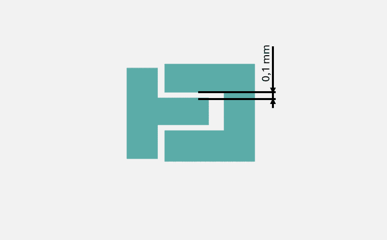
Loose connections and press fits
A gap of 0.1 mm between a male and female component creates a loose connection. Without such a gap, a press fit is created.

Joints
Joints can be manufactured directly in the SLS process. This makes it possible to produce components with high functional integration directly from 3D data. We recommend a gap of 0.4 mm for joints that are built in the X, Y, or Z direction.
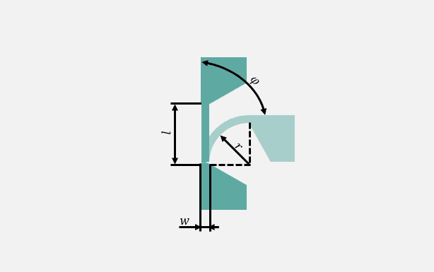
Film hinges
SLS components with functional film hinges can be manufactured from the materials PA2200, PA2201 and PA1101. PA1101 is best suited for the implementation of film hinges due to its low modulus of elasticity. Film hinges should be designed openly and attached to thick wall thicknesses if possible. The following guidelines apply to the construction of film hinges with a radius 𝒓 of 0.5 mm:
| Opening angle 𝜑 | Length 𝑙 | Wall thickness 𝒘 |
|---|---|---|
| 180° | 1.6 mm | 0.3 to 0.45 mm |
| 90° | 0.7 mm | 0.3 to 0.45 mm |

Font sizes
The minimum manufacturable font size (raised and recessed) is 10 in all build directions. Font size 10 corresponds approximately to a font height of 3.5 mm. The inscription should be at least 0.5 mm recessed or raised. It is also best to use a font without serifs, such as Arial or Calibri.

Tolerances
SLS components can only meet tolerances with symmetrical dimensions, e.g. 20 ± 0.2 mm. The tolerance range always depends on the geometry and material. Guidelines for the tolerance range for laser sintering always depend on the nominal dimension and are in the following range:
| Nominal Dimension | Tolerance Range |
|---|---|
| 0 to 30 mm | ± 0.2 mm |
| 30 to 100 mm | ± 0.3 mm
|
| From 100 mm | ± 0.3% of the nominal dimension |

Residual powder removal
To remove the residual powder from our SLS components, all components are first glass bead blasted and then blown off with compressed air. Residual powder that is trapped in inner chambers cannot be removed in this process. Thin and long inner tubes, as well as complex inner structures, make residual powder removal more difficult. If residual powder still remains in inner channels, we work with ultrasound, thin wires and thin compressed air hoses.

Distortion
Thick-walled components or components with large surfaces in combination with thin wall thicknesses are susceptible to distortion due to the process. To reduce distortion in thick-walled components, we can simply incorporate honeycomb structures – just contact us. Reinforcing large surfaces, e.g. with ribs, can also significantly minimize distortion effects.
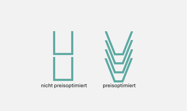
Price optimization
Use geometries that allow the components to be nested inside each other as much as possible in order to save space in the build space and thus costs. The more components we get into a build space, the lower the price per piece. The component on the image on the left, for example, can be stacked on top of each other, so that the build space can be ideally utilized.